

AC Dimmer Modules with Arduino and ESP
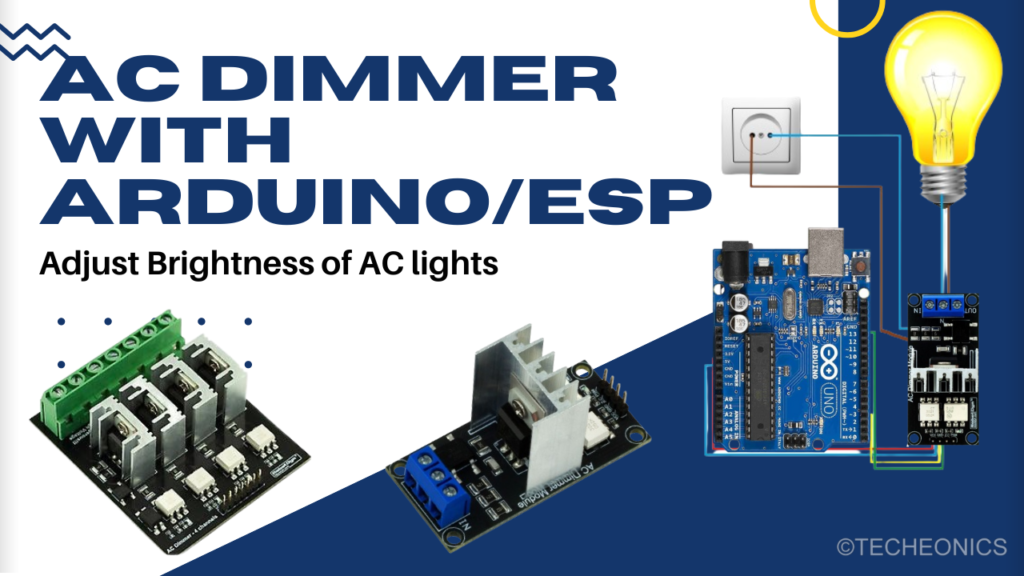
Adjust the brightness of AC-powered lights
In today’s DIY electronics scene, controlling AC light brightness using an AC dimmer module and Arduino is a popular and practical project. This article delves into the details of the AC dimmer module, its features, and how to use it to control AC lights with Arduino. We’ll also provide step-by-step instructions and example codes to make your project a success. AC Dimmer Modules with Arduino and ESP
What is an AC Dimmer Module?
An AC dimmer module allows you to adjust the brightness of AC-powered lights. These modules come in various configurations, including single-channel and four-channel versions, to suit different project needs. Key features of these modules include:
- Compatibility: Works with most AC light bulbs.
- Channels: Available in one-channel and four-channel versions.
- Control: Can be controlled via microcontrollers like Arduino, ESP,STM,Pi, etc.
- Safety: Built-in features for safe operation.
Availability
You can find AC dimmer modules on popular electronics component websites like SparkFun, Adafruit, or Amazon. Make sure to choose the one that fits your project’s requirements. For this guide, we’re using the RobotDyn AC Light Dimmer Module.
How Does an AC Dimmer Module Work?
The core of an AC dimmer module is the TRIAC, a semiconductor device that controls the power flow to the load (light bulb) by adjusting the phase angle of the AC signal. Here’s a simplified breakdown of the process:
- Zero Crossing Detection: The module detects the zero-crossing point of the AC signal.
- Phase Control: By controlling the phase angle at which the triac is triggered, the module adjusts the amount of power delivered to the light bulb, thereby dimming it.
Components of the AC Dimmer Module
- Triac: Controls the power flow to the AC load.
- Zero-Crossing Detector: Detects the point where the AC signal crosses zero voltage.
- Microcontroller Interface: Allows connection to microcontrollers like Arduino, ESP32, etc.
- PWM Control: Uses Pulse Width Modulation (PWM) to adjust the brightness.
Pinout and Functionality
- AC Input/Output Terminals: Connects to the AC power source and the light bulb.
- Control Pins: Typically includes pins for VCC(5V), PWM input, zero-crossing detection, and ground.
Connecting the Wiring
To set up the AC dimmer module with your Arduino or any other microcontroller, follow these detailed wiring instructions:
- VCC: Connect the VCC pin of the dimmer module to the 5V pin on the Arduino or corresponding microcontroller.
- Ground: Connect the GND pin of the dimmer module to the GND pin on the Arduino or microcontroller.
- PWM (PSM) Pin : Connect the PWM pin of the dimmer module to the PWM-capable pin on the Arduino (e.g., pin 3). This pin controls the brightness of the AC load.
- Zero Crossing Detection (ZC) Pin: Connect the ZC pin of the dimmer module to the pin defined in the program (e.g., pin 2 on the Arduino).
For the AC connections:
- AC Input Terminals: Connect the AC input terminals to your AC power source.
- AC Output Terminals: Connect the AC output terminals to the AC light bulb or load you intend to control.
Setting Up the Arduino Environment
To get started with your AC dimmer project, you need to set up your Arduino environment and install the necessary library. Follow these steps:
- Install the Library: Download the AC dimmer library from the provided GitHub repository. Open the Arduino IDE, go to
Sketch > Include Library > Add .ZIP Library, and select the downloaded ZIP file. - Example Codes: The repository includes example codes for controlling the dimmer module via the serial monitor and a potentiometer.
Example Code 1: Controlling the Module from Serial Monitor
Here’s a simple example code to control the AC dimmer module using the Arduino serial monitor:
#include <RBDdimmer.h>

// Dimmer object initialization
const int dimmerPin = 3;  // Dimmer module connected to pin 3
dimmerLamp dimmer(dimmerPin);

void setup() {
  Serial.begin(9600);
  dimmer.begin(NORMAL_MODE, ON); // Initialize dimmer
}

void loop() {
  if (Serial.available()) {
    int brightness = Serial.parseInt(); // Read value from serial monitor
    if (brightness >= 0 && brightness <= 100) {
      dimmer.setPower(brightness); // Set dimmer power
      Serial.println("Brightness set to " + String(brightness) + "%");
    }
  }
}
Step-by-Step Guide to Connect and Code
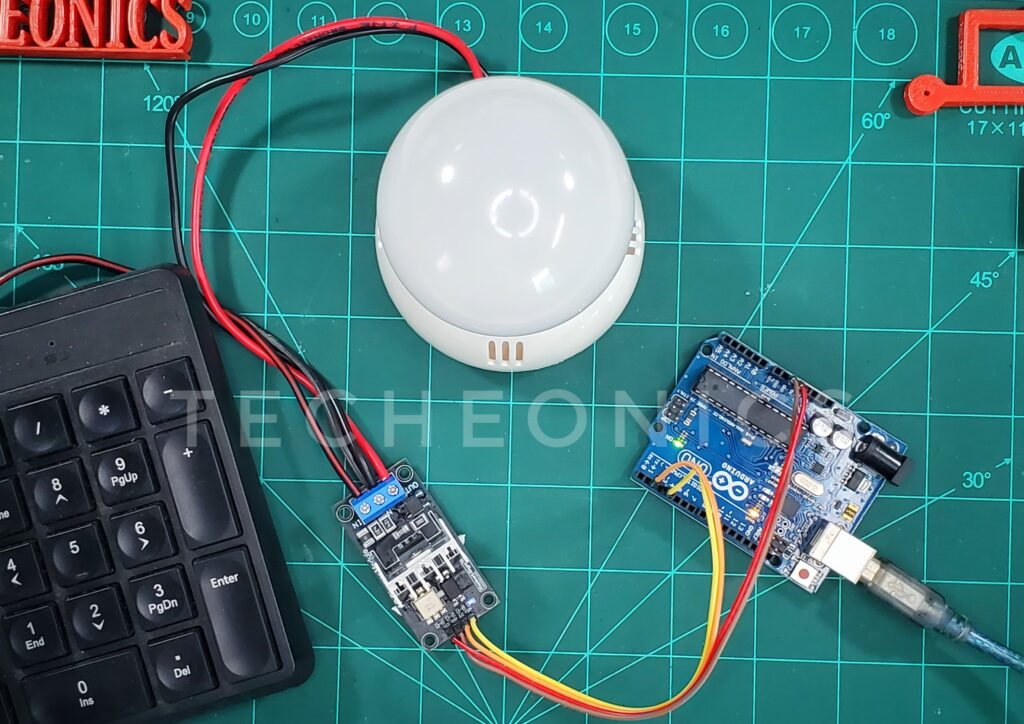
- Circuit Connection:
- Single-Channel Module:
- Connect the dimmer pin to pin 3 on the Arduino.
- Connect the light bulb to the output terminals of the dimming module.
- Ensure the module’s power connections are properly made.
- Four-Channel Module:
- Repeat the above steps for each channel, connecting to the corresponding Arduino pins.
- Single-Channel Module:
- Loading the Code:
- Open the Arduino IDE and upload one of the provided example codes.
- For the serial monitor example, open the serial monitor (Ctrl+Shift+M) and input values between 0 and 100 to adjust brightness.
- Testing:
- Once the code is uploaded, connect your setup to an AC power source.
- Observe the light bulb’s brightness change as you interact with the Arduino controls.
Example Code: Controlling Brightness with a Potentiometer
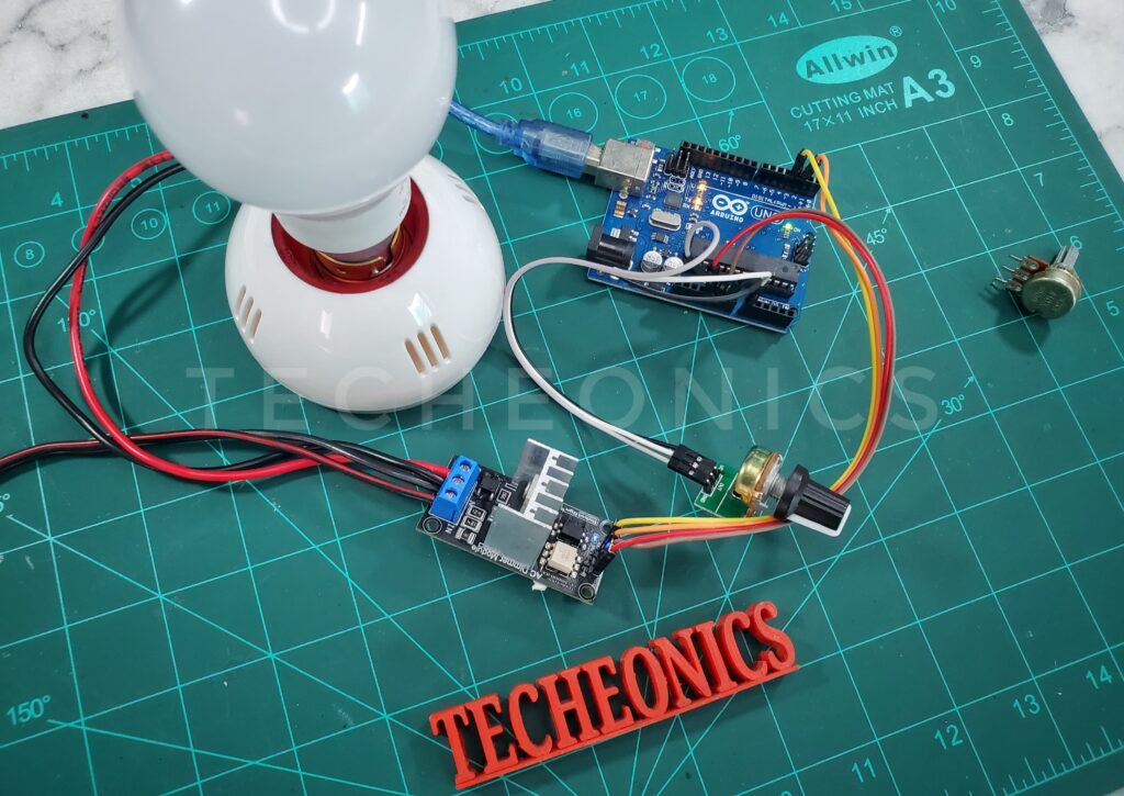
To add a potentiometer to your circuit, follow these steps:
- Connect the Potentiometer:
- One Pin to 5V: Connect one pin of the potentiometer to the 5V pin on the Arduino.
- Another Pin to GND: Connect the second pin of the potentiometer to the GND pin on the Arduino.
- Center Pin to A0: Connect the center pin (wiper) of the potentiometer to the A0 analog input pin on the Arduino.
Here’s the code that integrates the potentiometer to control the brightness of the AC light:
#include <RBDdimmer.h>

const int dimmerPin = 3;  // Dimmer module connected to pin 3
const int potPin = A0;    // Potentiometer connected to analog pin A0
const int zcPin = 2;      // Zero-crossing detection connected to pin 2

dimmerLamp dimmer(dimmerPin, zcPin);

void setup() {
  dimmer.begin(NORMAL_MODE, ON); // Initialize dimmer
}

void loop() {
  int potValue = analogRead(potPin); // Read potentiometer value
  int brightness = map(potValue, 0, 1023, 0, 100); // Map value to 0-100%
  dimmer.setPower(brightness); // Set dimmer power
  delay(50);
}
Explaining the Potentiometer Code
In this example, the potentiometer is used to control the brightness of the AC light:
- Include Library: The RBDdimmer library is included to handle the dimming functions.
- Initialize Dimmer: The
dimmerLampobject is initialized with the PWM pin and zero-crossing pin. - Setup Function: The
beginmethod initializes the dimmer module in normal mode. - Loop Function:
- Read Potentiometer Value: The analog value from the potentiometer is read using
analogRead(potPin). - Map Value: The potentiometer value, which ranges from 0 to 1023, is mapped to a brightness value between 0 and 100 using the
mapfunction. - Set Brightness: The
setPowermethod is used to set the brightness of the AC light based on the mapped potentiometer value. - Delay: A short delay of 50 milliseconds is added to make the dimming transition smoother.
- Read Potentiometer Value: The analog value from the potentiometer is read using
These additional details should help you complete the setup and understand how to integrate the potentiometer into your AC dimmer project. For further assistance, refer to the GitHub repository.
Additional Microcontroller Compatibility
This project is compatible with various microcontrollers, including ESP32 and ESP8266. When using these boards, ensure you connect the PWM pin correctly according to their pinout diagrams. For ESP32, you can use any GPIO pin that supports PWM.
Conclusion
By following this guide, you can successfully control the brightness of AC lights using an AC dimmER module and Arduino. This project not only enhances your understanding of AC power control but also opens up possibilities for more advanced home automation projects.
Don’t forget to watch the accompanying YouTube video for a visual demonstration of the project.
If you have any questions or run into issues, check out the provided GitHub repository for more resources and community support. Happy tinkering!
FAQs
Q: Can I use AC Dimmer module with any light bulb?
A: Most standard AC light bulbs are compatible, but it’s always best to go with Dimmer specifications bulbs.
Q: Is this project safe to perform at home?
A: Yes, as long as you follow the instructions carefully and take necessary precautions when dealing with AC power.
Q: Where can I find the AC dimmer module?
A: These modules are available on various electronics component websites like SparkFun, Adafruit, and Amazon.