

Build A Line-Following Robot Using IntelliBot V1
Introduction
Line-following robots are among the most engaging and educational robotics projects for beginners. They offer a hands-on introduction to the fundamentals of electronics, sensors, and programming. In this comprehensive guide, we’ll walk you through building a line-following robot using the Intelli Bot V1 DIY Robotics Kit, which includes an Arduino Nano, two IR sensors, and a motor driver. This project is ideal for those eager to explore the exciting world of robotics and microcontrollers.
Table of Contents:
- What is a Line-Following Robot?
- Understanding the Working Principle
- Wiring the Components
- Programming the Intelli Bot v1
- Testing and Calibration
- Precautions
- Final Thoughts
What is a Line-Following Robot?
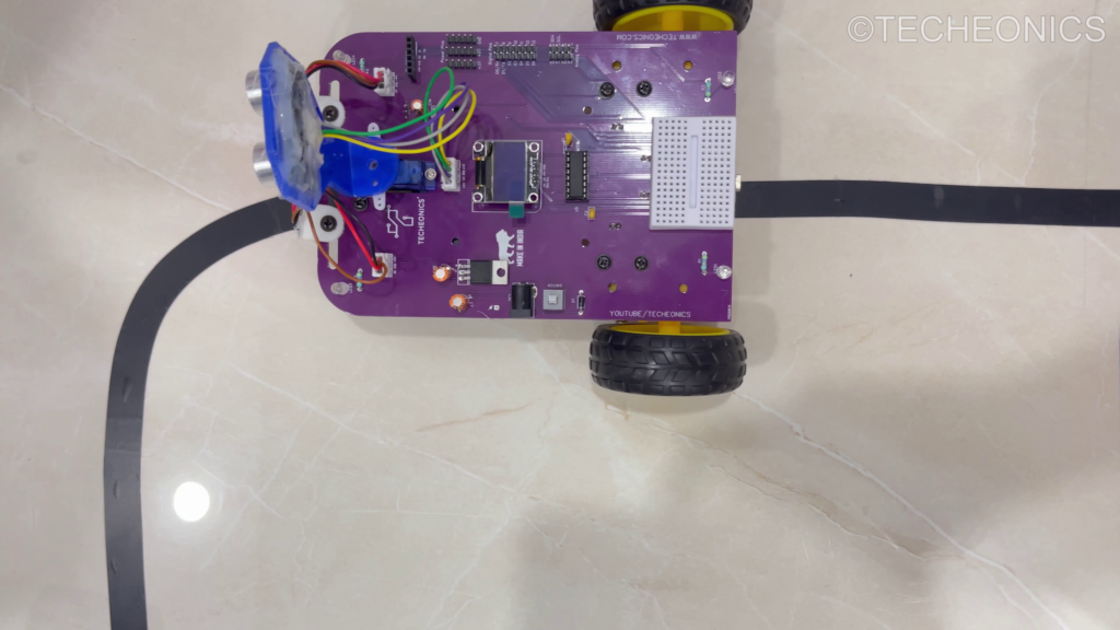
A line-following robot is a type of autonomous robot that can detect and follow a line, usually a black line on a white surface or vice versa. The robot uses infrared (IR) sensors to detect the line and adjusts its movements accordingly to stay on track.
Understanding the Working Principle
A line-following robot operates by detecting a line on the ground using IR sensors. These sensors are strategically placed on the front of the robot to differentiate between the line and the surrounding surface. The robot’s behavior is determined based on the sensor readings:
- Detecting Black Line: When the sensors detect a black line, the robot must adjust its direction to stay on the path.
- Detecting White Surface: When the sensors detect a white surface, the robot continues to move forward.
By analyzing the signals from both sensors, the robot can make decisions to move forward, turn left, or turn right to remain on the designated path.
Wiring the Components
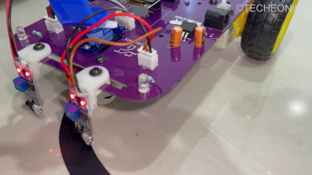
1. IR Sensors
- Sensor 1: Connect IR Sensor 1 to the designated IR port on the PCB. Ensure the notch is correctly aligned.
- Sensor 2: Connect IR Sensor 2 to the IR port on the PCB. Verify the notch alignment as well.
2. Motors
- Mounting Motors: Secure the motors onto the PCB.
- Connecting Motors: Attach the cables to Motor 1 and Motor 2 on the PCB.
3. Arduino Nano
- Mount Arduino Nano: Place the Arduino Nano onto the PCB.
- Power Supply: Insert the 18650 3.7V lithium-ion cells into the cell holder to power the robot.
Programming the Arduino Nano
With the wiring complete, it’s time to program the Arduino Nano. The logic for a basic line-following robot is as follows:
- Both Sensors Detect Line: Move the robot forward.
- Left Sensor Detects Line: Turn the robot left.
- Right Sensor Detects Line: Turn the robot right.
- Neither Sensor Detects Line: Stop or perform a corrective action.
We’ll use the IntelliBot_v1 library, which simplifies controlling motors and sensors by providing pre-built functions like motor movements (forward(), left(), right(), etc.).
Here is a sample code to achieve this functionality:
#include <IntelliBot_v1.h>

// Create instances of Motors and IR_Sensors
Motors myMotors;
IR_Sensors myIRSensors;

void setup() {
    // Initialize the motors and sensors
    myMotors.init();
    myIRSensors.init();
}

void loop() {
    // Read the IR sensor values
    myIRSensors.readLeftIR();
    myIRSensors.readRightIR();

    byte leftIR = myIRSensors.getLeftIR();
    byte rightIR = myIRSensors.getRightIR();

    // Line following logic
    if (leftIR == myIRSensors.whiteColor && rightIR == myIRSensors.whiteColor) {
        // Both sensors detect white, move forward
        myMotors.forward();
    } else if (leftIR == myIRSensors.whiteColor && rightIR == myIRSensors.blackColor) {
        // Left sensor detects white, right sensor detects black, turn right
        myMotors.right();
    } else if (leftIR == myIRSensors.blackColor && rightIR == myIRSensors.whiteColor) {
        // Left sensor detects black, right sensor detects white, turn left
        myMotors.left();
    } else {
        // Both sensors detect white, stop or brake
        myMotors.brake();
    }
}
Explanation:
- The code starts by importing the IntelliBot_v1 library.
- Motors and IR_Sensors objects are created to control the motors and sensors.
- The
setup()function initializes the motors and sensors. - The
loop()function continuously reads the values from the IR sensors and decides the robot’s movement based on the sensor inputs:- Both sensors white: Move forward.
- Left white, right black: Turn right.
- Left black, right white: Turn left.
- Both black: Stop.
Testing and Calibration
After uploading the code to your Arduino Nano, place your robot on a track with a visible line. Observe how the robot performs and make adjustments as needed:
- Adjust Sensor Sensitivity: Fine-tune the IR sensors to ensure accurate line detection.
- Tweak the Code: Modify the code if the robot does not follow the line correctly.
Precautions
- Secure Connections: Verify that all connections are secure to prevent intermittent issues.
- Correct Pin Assignments: Ensure each component is connected to the correct pins to avoid malfunctions.
- Sensor Placement: Position the IR sensors 1-2 cm from the ground and ensure they are aligned properly for accurate line detection.
Conclusion
Building a line-following robot with the Intelli Bot V1 DIY Robotics Kit is a fantastic way to learn about robotics, electronics, and programming. By following this guide, you’ll gain hands-on experience and develop a solid understanding of how to create autonomous systems. Enjoy the process of building and refining your robot!
Happy building!