

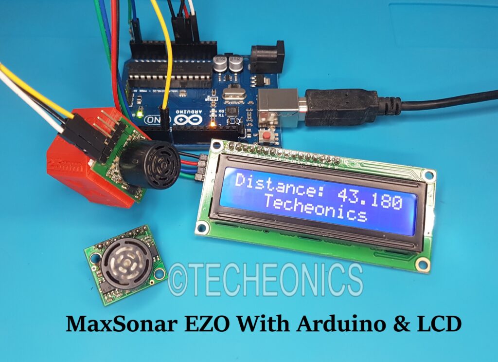
MaxSonar Ultrasonics Sensor With Arduino
I will show you how we can program/use the MaxSonar EZ0 sensor With Arduino.
The EZ0 Sonar detects objects from 0-inches to 254-inches (6.45-meters) and provides sonar range information from 6-inches out to 254-inches with 1-inch resolution. Objects from 0-inches to 6-inches typically range as 6- inches
The MaxSonar provides very short to long-range detection and ranging, in an incredibly small package. It can detect objects from 0-inches to 254-inches (6.45-meters) and provides sonar range information from 6-inches out to 254-inches with 1-inch resolution. (Objects from 0 inches to 6-inches range as 6-inches.) The interface output formats included are pulse width output (PWM), analog voltage output (Vcc/512 volts per inch), and serial digital output (9600 baud).

This sensor Has 3 Output formats To interface with:-
1 ) Analog interface.
2) Pulse width Modulation “PW”.
3) Serial Interface.
Material:-
1) Arduino Board ” I used Arduino UNO”.
4)Wires and BreadBoard.
Interface The Sensor
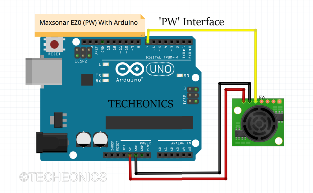
We will use the ‘PW’ pin on the sensor to interface with Arduino
Pulse width “PW” Is the way to communicate with this sensor.
This pin outputs a pulse-width representation of range.
The distance can be calculated using the scale factor of 147uS per inch.
So using Pulse in to calculate the distance.
MaxSonar EZ0 With Arduino & LCD
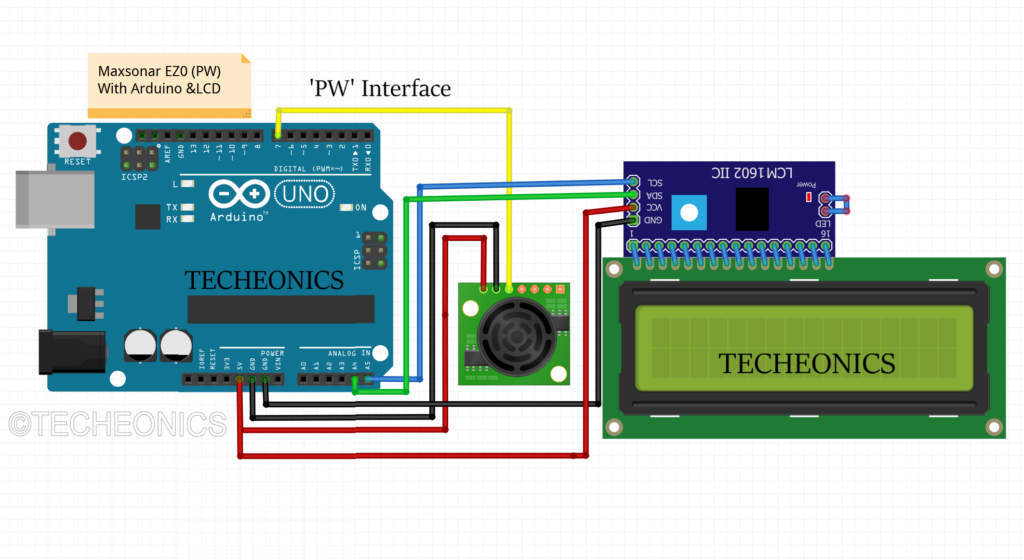
Connections
VCC = 5V
GND = GND
SDA = A4
SCL = A5
We can add an LCD Display with I2C Module to Display the output on it.
Analog & Serial Interface of Maxsonar
Analog Interface
The Analog Interface is the easiest way to communicate with this sensor, there is a directly proportional between Distance and Output voltage. Outputs analog voltage with a scaling factor of (Vcc/512) per inch. For example, a voltage supply of 5V yields ~9.8mV/inch, a voltage supply of 3.3 V yields ~6.4mV/inch. The analog output voltage is not accurate rather than PW And serial. so I prefer to use PW or serial
Serial Interface
For the Serial interface method, we will use the SoftwareSerial library to write the code for this sensor, And we will Connect D4 With BW, Leave it open, or hold it low for serial output on the TX output. The output is an ASCII capital “R” which equal 0x52, followed by three ASCII character digits representing the range in inches up to a maximum of 255, followed by a carriage return (ASCII 13 or 0x0D)
Check Out Other Projects – DFROBOT TDS Meter Sensor With Arduino & LCD Measure Water Quality